Ultra Low-Power 5V Regulator

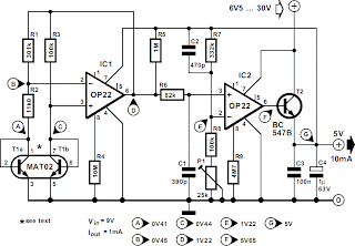
The current drain of the regulator is minute compared with that of, say, a 78L05: at an input voltage of 9 V and open-circuit output, it is just under 50 µA. The circuit consists of a straightforward bandgap reference based on T1 and IC1, followed by an amplifier formed by IC2 and T1. The reference voltage is about 1.22 V, which is raised by IC2 to 5 V. The output voltage can be set to exactly 5 V with P1. The input voltage may lie between 6.5 V and 30 V. The maximum output current with the present configuration and component values as specified is about 10 mA.
Ultra Low-Power 5V Regulator
For optimum performance, T1a and T1b need to be identical, which is why a dual transtor Type MAT02 is used. Other types that may be used are the MAT01, SSM2210 or LM394. In principle, two standard BC transistors may be used, provided they are selected for identical threshold voltage. Circuits IC1 and IC2 are programmable op amps Type OP22. In the case of IC2 this has the benefit that the peak output current can be set readily by altering the supply current to the op amp with R9. The level of the current may be between 500 nA and 400 µA.

Ultra Low-Power 5V Regulator Circuit DiagramBear in mind that a larger output current requires the use of a more highly rated output transistor. Filter R6-C1 prevents any spurious pulses reaching the input of IC2. Capacitor C2 improves the stability of the regulator, particularly with maximum pulse loading. Note that the circuit has a high resistance, so that it is advisable to house it in a screened enclosure to prevent undesired magnetic and electromagnetic interference being coupled to the circuit. The regulator was tested with a direct load current of 1 mA on which was superimposed a square-wave current of 10 mA. The test results are summarized in the table, in which Ig represents the current drawn by the circuit.

Electronic Torricelli Barometer

Although it does not have the same charm as real mercury barometers with long glass tubes on pieces of carved and polished wood, the Torricelli barometer discussed here is a functional equivalent and electronic replica of the Torricelli barometer. Actually, rather than displaying the atmospheric pressure on the traditional digital displays, we preferred to reproduce the general look of this respected predecessor of electronic barometers.

The mercury tube is, of course, replaced by a simple LED scale which, if not as beautiful, is still less toxic for the environment in case of breakage. As indicated on the drawing, the pressure sensor utilized is a Motorola MPX2200AP. This circuit is adapted for measuring absolute pressure and has a range well suited for atmospheric pressure. Without entering too deep into the technical details, such sensors deliver an output of voltage proportional not only to the measured pressure but, unfortunately, to their supply voltage as well.

Hence they must be powered from a stable voltage which is ensured here by the use of IC1. Since the output of the MPX2200 is differential and at a very low level, we had to resort to the use of four operational amplifiers IC4.A to IC4.D, contained in one LM324, to obtain levels that can be processed easily. As long as potentiometer P1 is adjusted correctly, this group of operational amplifiers delivers a voltage of 1 volt per atmospheric pressure of 1,000 hPa to the LM3914.

Since the atmospheric pressure will be within the range 950 to 1040 hPa at sea level, we need to make an expanded-scale voltmeter with this LM3914 in order to better exploit the 10 LEDs that it can control. That is the role of resistors R7 and R8 which artificially raise the minimum voltage value the chip is capable of measuring. Consequently, we can ‘calibrate’ our LED scale with one LED per 10 hPa and thus benefit from a measurement range which extends from 950 hPa to 1040 hPa. In principle, you should not have a need to go beyond that in either direction.

The circuit may be conveniently powered from a 9-volt battery but only if used very occasionally. Since this is usually not the case for a barometer, we advise you to use a mains adaptor instead supplying approximately 9 volts. Calibration basically entails adjusting the potentiometer P1 to light the LED corresponding to the atmospheric pressure of your location at the time. Compare with an existing barometer or, even better, telephone the closest weather station. They will be happy to give you the information. After Evangelista Torricelli, 1608-1647, Italian physician who proved the existence of atmospheric pressure and invented the mercury barometer.
Author: Christian Tavernier - Copyright: Elektor Electronics Magazine

Infrared Proximity Detector Alarm

This circuit can be built from readily available low-cost components, some of which may even be hiding in your junkbox! The indicated value of 22 Ω for resistor R1 causes an average current of about 65 mA through infrared emitter D1. Because the IRED is pulsed at a duty factor of about 50% through the action of T1 and IC1, a peak current of 128 mA flows during every half cycle. This may seem a lot but in fact is well within the safe specification of the LD274. The LM567 PLL IC is configured to supply a switching frequency of about 20 kHz. When the infrared beam emitted by D1 is reflected by a nearby object, IC1, through receiver diode D2 and transistor T2, receives the recovered 20 kHz signal at its input, pin 3.

Infrared Proximity Detector Alarm Circuit Diagram


Because the ‘567 PLL is then locked, the IC output (pin 8), drops low, triggering the 555 chip in monostable mode (IC2) and so causing acoustic actuator Bz1 to sound. The monostable remains on as long as the reflected signal is being received. Because of the presence of T3, capacitor C5 is allowed to charge only when no signal is being received. In that condition, the 555 is turned off automatically after a time determined by R9-C5. Using the component values shown, this will be about 5 seconds. Obviously D1 and D2 should be mounted such that the latter can only pick up reflected infrared light.

The choice of the two infrared components used in this circuit will be uncritical but they must be ‘band’ compatible, i.e., generate (D1) and respond to (D2) the same wavelength. The operating point of the receiver input circuit is rather dependent on ambient day-light levels and the value of R4 may need to be adjusted a little to ensure a voltage of between 1.5 V and 4 V on the collector of T1 when no signal is being received. Some dc buzzers cause a lot of back-emf so it may be necessary to insert a diode in series with the output of IC1. If necessary, this diode should preferably be a Schottky type because of the inherent low voltage drop of about 0.4 V as opposed to 0.65 V for a typical small-signal silicon diode.

Momentary Switch Teamed With Latching Relay

This circuit allows an SPST momentary pushbutton to act as a push-on push-off switch, using a DPDT latching (bi-stable) relay. It was originally intended to allow a single pushbutton switch on the dash of a vintage car to provide a latched function. The relay only draws current when it is being switched. At other times, the only current drain on the 12V supply is the leakage current of one 22µF capacitor, which is very low. It works as follows.

Assume that initially the latching relay is in the reset state, with pins 4 and 6 connected together. In this state, C2 charges up to +12V via 2.2kO resistor R2 while capacitor C1 remains discharged as it is not connected to the 12V supply. If S1 is pressed, C2 discharges via the relay’s “set” coil, diode D2 and S1. This switches the relay into its set position, connecting pins 4 and 8. C1 then begins to charge via R1. While S1 is being held down, the relay does not return to the reset position because the current supplied via R1 is insufficient for the coil to latch the armature. As soon as S1 is released, current no longer flows though the coil so C1 can finish charging, ready for the next button press.

Circuit diagram:
Momentary switch teamed with latching relay circuit schematic
Momentary Switch Circuit Diagram Teamed With Latching Relay

Once the relay has switched and C1 has finished charging, pressing S1 again causes the relay to switch back to the reset state via the same process. The unused set of relay contacts can be used as an SPST or SPDT switch. The circuit as shown has been tested with the Jaycar SY4060 relay. It will work with other DPDT twin-coil latching relays but the resistor and capacitor values may need to be adjusted to suit. Relays with lower resistance coils will need larger value capacitors and smaller value resistors.
Author: Merv Thomas - Copyright: Silicon Chip Electronics Magazine

Two-Cell LED Torch

It sometimes comes as a bit of a shock the first time you need to replace the batteries in an LED torch and find that they are not the usual supermarket grade alkaline batteries but in fact expensive Lithium cells. The torch may have been a give away at an advertising promo but now you discover that the cost of a replacement battery is more than the torch is worth. Before you consign the torch to the waste bin take a look at this circuit. It uses a classic two-transistor astable multivibrator configuration to drive the LEDs via a transformer from two standard 1.5 V alkaline batteries.

The operating principle of the multivibrator has been well documented and with the components specified here it produces a square wave output with a frequency of around 800 Hz. This signal is used to drive a small transformer with its output across two LEDs connected in series. Conrad Electronics supplied the transformer used in the original circuit. The windings have a 1:5 ratio. The complete specification is available on the (German) company website at www.conrad.de part no. 516236. It isn’t essential to use the same transformer so any similar model with the same specification will be acceptable.
Two-Cell LED Torch

The LEDs are driven by an alternating voltage and they will only conduct in the half of the waveform when they are forward biased. Try reversing both LEDs to see if they light more brightly. Make sure that the transformer is fitted correctly; use an ohmmeter to check the resistance of the primary and secondary windings if you are unsure which is which. The load impedance for the left hand transistor is formed by L in series with the 1N4002 diode. The inductance of L isn’t critical and can be reduced to 3.3 mH if necessary. The impedance of the transformer secondary winding ensures that a resistor is not required in series with the LEDs.

Unlike filament type light sources, white LEDs are manufactured with a built-in reflector that directs the light forward so an additional external reflector or lens glass is not required. The LEDs can be mounted so that both beams point at the same spot or they can be angled to give a wider area of illumination depending on your needs. Current consumption of the circuit is approximately 50 mA and the design is even capable of producing a useful light output when the battery voltage has fallen to 1 V. The circuit can be powered either by two AAA or AA size alkaline cells connected in series or alternatively with two rechargeable NiMH cells.

Cat And Dog Repellent

The electronic dog repellent circuit diagram below is a high output ultrasonic transmitter which is primarily intended to act as a dog and cat repeller, which can be used individuals to act as a deterrent against some animals. It should NOT be relied upon as a defence against aggressive dogs but it may help distract them or encourage them to go away and do not consider this as an electronic pest repeller. The ultrasonic dog repellant uses a standard 555 timer IC1 set up as an oscillator using a single RC network to give a 40 kHz square wave with equal mark/space ratio.

This frequency is above the hearing threshold for humans but is known to be irritating frequency for dog and cats. Since the maximum current that a 555 timer can supply is 200mA an amplifier stage was required so a high-power H-bridge network was devised, formed by 4 transistors TR1 to TR4. A second timer IC2 forms a buffer amplifier that feeds one input of the H-bridge driver, with an inverted waveform to that of IC1 output being fed to the opposite input of the H-bridge.

Circuit diagram:Cat And Dog Repellent
Cat And Dog Repellent Circuit Diagram

This means that conduction occurs through the complementary pairs of TR1/TR4 and TR2/TR3 on alternate marks and spaces, effectively doubling the voltage across the ultrasonic transducer, LS1. This is optimised to generate a high output at ultrasonic frequencies. This configuration was tested by decreasing the frequency of the oscillator to an audible level and replacing the ultrasonic transducer with a loudspeaker; the results were astounding. If the dog repellent circuit was fed by a bench power supply rather than a battery that restrict the available current, the output reached 110dB with 4A running through the speaker which is plenty loud enough!

The Dog and Cat repellant was activated using a normal open switch S1 to control the current consumption, but many forms of automatic switching could be used such as pressure sensitive mats, light beams or PIR sensors. Thus it could be utilise as part of a dog or cat deterrent system to help prevent unwanted damage to gardens or flowerbeds, or a battery powered version can be carried for portable use. Consider also using a lead-acid battery if desired, and a single chip version could be built using the 556 dual timer IC to save space and improve battery life.

Simple NiCd Battery Charger

A simple NiCd charger can be built using ‘junk box’ components and an inexpensive LM317 or 78xx voltage regulator. Using a current limiter composed of R3 and a transistor, it can charge as many cells as desired until a ‘fully charged’ voltage determined by the voltage regulator is reached, and it indicates whether it is charging or has reached the fully charged state. If the storage capacitor (C1) is omitted, pulsed charging takes place. In this mode, a higher charging current can be used, with all of the control characteristics remaining the same. The operation of the circuit is quite simple. If the cells are not fully charged, a charging current flows freely from the voltage regulator, although it is limited by resistor R3 and transistor T1.
Simple NiCd Battery Charger

The limit is set by the formula Imax ≈ (0.6 V) ÷ R3 For Imax = 200 mA, this yields R3 = 3 Ω. The LED is on if current limiting is active, which also means that the cells are not yet fully charged. The potential on the reference lead of the voltage regulator is raised by approximately 2.9 V due to the voltage across the LED. This leads to a requirement for a certain minimum number of cells. For an LM317, the voltage between the reference lead and the output is 1.25 V, which means at least three cells must be charged (3 × 1.45 V > 2.9 V + 1.25 V). For a 78xx with a voltage drop of around 3 V (plus 2.9 V), the minimum number is four cells.

When the cells are almost fully charged, the current gradually drops, so the current limiter becomes inactive and the LED goes out. In this state, the voltage on the reference lead of the regulator depends only on voltage divider R1/R2. For a 7805 regulator, the value of R2 is selected such that the current through it is 6 mA. Together with the current through the regulator (around 4 mA), this yields a current of around 10 mA through R1. If the voltage across R1 is 4 V (9 V – 5 V), this yields a value of 390 Ω. The end-of-charge voltage can thus be set to approximately 8.9 V. As the current through the regulator depends on the device manufacturer and the load, the value of R1 must be adjusted as necessary. The value of the storage capacitor must be matched to the selected charging current. As already mentioned, it can also be omitted for pulse charging.

Car Interior Lights Delay

Most cars do not have delayed interior lights. The circuit presented can put this right. It switches the interior lights of a car on and off gradually. This makes it a lot easier, for instance, to find the ignition keyhole when the lights have gone off after the car door has been closed. Since the circuit must be operated by the door switch, a slight intervention in the wiring of this switch is unavoidable. When the car door is opened, the door switch closes the lights circuit to earth. When the door is closed (and the switch is open), transistor T1, whose base is linked to the switch, cuts off T2, so that the interior light remains off. When the switch closes (when the door is opened), the base of T1 is at earth level and the transistor is off.
Car Interior Lights Delay

Capacitor C1 is charged fairly rapidly via R3 and D1, whereupon T2 comes on so that the interior light is switched on. When the door is closed again, T1 conducts and stops the charging of C1. However, the capacitor is discharged fairly slowly via R5, so that T2 is not turned off immediately. This ensures that the interior light remains on for a little while and then goes out slowly. The time delays may be varied quite substantially by altering the values of R3, R5, and C1. Circuit IC2 may be one of many types of n-channel power MOSFET, but it should be able to handle drain-source voltages greater than 50 V. In the proto-type, a BUZ74 is used which can handle D-S voltages of up to 500 V.

Compressor For Electret Microphone

The ‘FM Remote Control Receiver’ (available on this website in Infra-red circuits section) has a connector where an analogue output is made available. To make a simple intercom or P.A. system the associated transmitter needs a microphone pre-amplifier that outputs a signal at the correct level. And that is exactly the function of this circuit. Actually, this design is adapted from a circuit published last year (‘AM Modulator for Intercom’). A few things have been changed so that it can work with the 5 V supply from the transmitter module. The OTA (IC1) used here is the single version (CA3080), which has slightly different characteristics from the dual CA3280.

Compressor For Electret Microphone

The quad opamp is the same rail-to-rail TS924IN, made by ST. The turnover frequency of the filter (3rd order 1 dB Chebyshev) has been increased slightly to improve the intelligibility of speech and is now about 5.5 kHz. The filter now amplifies the signal by a factor of 10. In practice it is possible that due to various tolerances and the fact that the opamp is not perfect, the filter characteristic shows some deviation from that required. In our prototype it was necessary to change R15 into 2k7 to straighten the response curve. The DC current variation at the output of the OTA and the resulting offset variation at the output of current/voltage converter IC2d is such that the gain of IC2d has to be substantially smaller than in the ‘old’ design.

Otherwise the output could easily rise to the supply voltage at low signal levels. The value of R6 has therefore been made smaller by a factor of 10. This has reduced the gain of the circuit by 20 dB, which is compensated for in the filter. The amplitude of the signal from IC2d is fed back as a control current to the OTA by peak rectifier D1/C3 and inverting amplifier IC2b. R7 limits the loading on IC2d. P1 can be used to adjust the amplifier between a fixed gain and maximum compression. Figure A shows clearly what effect the circuit has. 0 dBr corresponds to 100 mV. The maximum gain, with P1 set to maximum compression, is about 48 dB (250 Ω) for small signals.

Compressor For Electret MicrophoneThe minimum gain is about 20 dB (10 Ω). The OTA is then slightly overdriven and the distortion becomes several percent! With a fixed gain selected (P1 shorted) the gain is about 42 dB (125 ×). The middle curve was measured with P1 in its central position. The curve drawn for a fixed gain (the straight line) doesn’t finish at the edge of the graph because the end of the line corresponds to the maximum possible output level, which is 25 dBr (≈1.76 V or 5 / 2√2). Figure B shows the frequency response. The low turnover frequency is mainly determined by C8 (and to a lesser extent by C1) and is about 120 Hz.

The current consumption is about 7 mA When the circuit is battery powered we recommend the use of three AA cells, because the circuit still works perfectly at 4.5 V. If you want to use a higher supply voltage (maximum 12 V for the de TS924IN and 30 V for the CA3080, but you should also think of the voltage across the electret microphone!) you have to keep in mind that the maximum current through R9 (which is IABC) is only 2 mA. When we consider a maximum chosen current of 1 mA and the maximum output voltage of IC2b (half the supply voltage, which is 2.5 V), then the value of R9 should be (2.5 – 0.7) V / 1 mA = 1.8 kΩ. The value of 0.7 V corresponds to the potential between pin 5 and earth.

Compressor For Electret MicrophoneFor a larger safety margin R9 is calculated with the full supply voltage and a current of 2 mA: (5 – 0.7) V / 2 mA = 2k2 (rounded upwards). Of course the regulation will then be different (a little less gain). This circuit and the transmitter module can therefore be fed from the same 5 V supply. Because the transmitter requires a DC offset at its input, a resistor is connected to +5 V via a jumper, which biases the output to half the supply voltage. With the jumper open R17 functions as a load resistor when the output is not connected, because C9 still has to charge up even without a load. If you’re designing a PCB for this compressor then it makes sense to include the transmitter module as well. The current consumption then increases by about 10 mA.
Author: T. Giesberts - Copyright: Elektor Electronics

Electronics Projects

Pulpit rock