Disposable Batteries Recharger


We do know that times can get pretty hard for some of us out there, especially when you are out of a job for the longest time and your savings have just about run out. Well, that would mean being even more prudent with every single penny that you spend, and there are many ways to do so. In the case of using disposable batteries, there might be a different method to prolong the life of these puppies even when others have long given up on them. How is that possible, you ask? Well, this is where the $79.95 Disposable Batteries Recharger comes in handy.

Disposable Batteries Recharger

The Disposable Batteries Recharger happens to have enough storage space to revitalize up to eight disposable batteries simultaneously. The device itself will feature a sophisticated microprocessor and proprietary charging technology that will be able to automatically identify battery types as well as their conditions before the charging process begins. The unit itself will be able to recharge batteries in one to eight hours depending on the type and size, and it also has the ability to revitalize alkaline batteries up to 10 times.

The eight charging slots has enough room to accommodate half a dozen AAA, AA, A, C, or D batteries and two 9-volt batteries, where it will play nice with alkaline, NiMH, or NiCd batteries. The inclusion of a built-in LCD will let you see the batteries’ charge levels. Man, I wish I had this back when I was a wee lad and was eating through AA batteries like nobody’s business on my Game Boy.

6-Channel Running Light

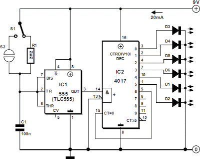
The circuit of the running light comprises two integrated circuits (ICs), a resistor, a capacitor and seven light-emitting diodes (LEDs), Decade scaler IC2 ensures that the LEDs light sequentially. The rate at which this happens is determined by the clock at pin 14. The clock is generated by IC1, which is arranged as an astable multivibrator. Its frequency is determined by R1-C1.
6-Channel Running Light
6-Channel Running Light Circuit Diagram
The touch switch, consisting of two small metal disks is optional. When switch S1 is in position ‘off’, the circuit may be actuated by the touch switch. By the way, this enables the circuit to be used as an electronic die (in which case the LEDs have to be numbered from 1 to 6). The running light is powered by a 9 V battery or mains adapter. It draws a current not exceeding 20 mA.

Author: L. v/d Heeden
Copyright: Elektor Electronics 1998

Kisai Adjust LED Watch

If you have always wanted to have a cool looking timepiece that is extremely difficult to read, then you would not be able to go wrong with Tokyoflash’s collection of timepieces. Their latest addition to the collection would be the $178.99 TokyoFlash Kisai Adjust, where it will boast of a digital triangle time readout. You can opt to tell the time in either a horizontal or vertical display, depending on your cup of tea, and there are also half a dozen LED colors to choose from, with the option for multi-color transition thrown into the mix along as well.

Kisai Adjust LED Watch

Just how does the TokyoFlash Kisai Adjust work? Well, it will be able to show off the time in a non-stop array of changing mosaic of LED triangles. You can opt to have it shown off in either 12 or 24 hour modes, and some might say that the vertical mode makes it easier to read the time compared to the horizontal mode. Even more, when night falls, the Tokyoflash Kisai Adjust would feature a tiny fish that swims across your wrist, accompanied by random sparkles for that added touch of uniqueness that only Japan can offer. It will also be water resistant up to 3ATM, and has a stainless steel case, strap, and clasp.

Disposable Batteries Recharger

We do know that times can get pretty hard for some of us out there, especially when you are out of a job for the longest time and your savings have just about run out. Well, that would mean being even more prudent with every single penny that you spend, and there are many ways to do so. In the case of using disposable batteries, there might be a different method to prolong the life of these puppies even when others have long given up on them. How is that possible, you ask? Well, this is where the $79.95 Disposable Batteries Recharger comes in handy.

Disposable Batteries Recharger

The Disposable Batteries Recharger happens to have enough storage space to revitalize up to eight disposable batteries simultaneously. The device itself will feature a sophisticated microprocessor and proprietary charging technology that will be able to automatically identify battery types as well as their conditions before the charging process begins.

The unit itself will be able to recharge batteries in one to eight hours depending on the type and size, and it also has the ability to revitalize alkaline batteries up to 10 times. The eight charging slots has enough room to accommodate half a dozen AAA, AA, A, C, or D batteries and two 9-volt batteries, where it will play nice with alkaline, NiMH, or NiCd batteries. The inclusion of a built-in LCD will let you see the batteries’ charge levels. Man, I wish I had this back when I was a wee lad and was eating through AA batteries like nobody’s business on my Game Boy. [Via]

Mushkin Atom 3.0 USB flash drive introduced

I am quite sure that by now, many of us have already amassed quite a collection of USB flash drives over the months and years that have gone by. Hardly any conference or road show is devoid of a USB flash drive which more often than not contains the press release of a particular company, or a portfolio of new products. Having said that, it can be pretty difficult trying to keep track of just where exactly have you placed that particular file over in the myriad of USB flash drives that you have in your collection, and instead get a personal USB flash drive for yourself so that you can keep personal things private and secure.

Mushkin Atom 3.0 USB flash drive introduced

Just in case you are in the market scouting for a new USB flash drive, have you considered checking out the Mushkin Atom 3.0? The Mushkin Atom 3.0 USB flash drive will place plenty of emphasis on convenience, where it comes in an extremely small form factor which is slightly less than the size of your average quarter. All of this without having to sacrifice on performance, since the Mushkin Atom 3.0 will still be able to boast of USB 3.0 extreme performance even when exercising low power consumption. Apart from that, you do not have to worry about legacy systems, since the Atom USB 3.0 flash drive will still play nice with USB 2.0 and 1.1 ports.

Mushkin Atom 3.0 USB flash drive introduced

As for the 8GB model, it will feature 80MB/s read, 5.5MB/s write, and consumes 0.65W while idle, or 0.905W at load. There is also a 16GB flash drive model that boasts of 155MB/s read and 11.5MB/s write on 0.25W idle and 0.67W load. As for the 32GB model, it reads at 155MB/s with 21.5MB/s write, and low power consumption of 0.2475W when idle and 0.75W under load. Since it is so small, you can always opt to leave the Atom USB 3.0 flash drive in the USB port while working on-the-go without having to suffer from any obstruction. Notebook and Ultrabook owners, especially, would be able to appreciate its tiny design and performance. [Via]

BLU Life Pure Android Phone Announced

Following two budget-friendly smartphones, BLU announced its flag grade Android phone – Life Pure. If you need a high performance smartphone, let’s go on checking. BLU Life Pure is a 5-inch Android smartphone with flagship performance that measures 142 x 69.4 x 7.7mm and weights 128grams.

BLU Life Pure Android Phone Announced

ures ultra-slim and minimal design and runs on Google Android 4.2 Jelly Bean mobile operating system, moreover, Life Pure comes with MediaTek MT6589T Cortex-A7 1.5GHz quad-core processor with PowerVR SGX544 GPU, 2GB RAM, 32GB internal storage, 5-inch full HD display at 1080 x 1920 pixels resolution with 441 ppi, 5-megapixel front-facing camera capable of full HD imaging and 13-megapixel rear autofocus camera with a 5-element lens, BSI sensor and LED flash.

BLU Life Pure Android Phone Announced

The smartphone feat Apart from that, other specs include GPS, Bluetooth 4.0, WiFi, Hotspot, FM radio and 2000mAh rechargeable battery. BLU Life Pure Android phone comes in two colors and costs $349 USD.

Solar Powered Animal Scarer

Here is a solar powered Flasher to scare away the nocturnal animals like bats and cats from the farm yard or premises of the house. The brilliant multicolored flashes confuse these animals and they avoid the hostile situation. It is fully automatic, turns on in the evening and turns off in the morning.

The circuit has an LDR controlled oscillator built around the Binary counter IC CD 4060.The functioning of the IC is controlled through its reset pin 12. During day time, LDR conducts and keeps the reset pin of IC high so that it remains dormant. During night, LDR cease to conduct and the reset pin will be grounded through VR1. This triggers the IC and it stats oscillating using the components C1 and VR2. Output pins 7, 5 and 4 are used to power the LEDs strings.

VR1 adjusts the sensitivity of LDR and VR2, the flashing rate of LEDs. High bright Red, Blue and White LEDs are used in the circuit to give brilliant flashes. Red LEDs flash very fast, followed by blue and then White. White LEDs remains on for few seconds and provide light to a confined area. More LEDs can be added in the strings if desired. The circuit can also function with 12 volt DC.

Animal Repellent Circuit Diagram

Solar Powered Animal Scarer

The circuit uses a solar powered battery power supply. During daytime, battery charges through R1 and D1.Green LED indicates the charging mode. During night time current from the solar cell decreases and D1 reverse biases. At the same time D2 forward biases to provide power to the circuit. Resistor R1 restricts the charging current and the high value capacitor C1 is a buffer for current.

Animal Scarer Solar Power Supply

Solar Powered Animal Scarer


New Trent PowerPak Ultra Backup Battery

New Trent recently released a new power bank – PowerPak Ultra. If you like rugged design or need a large-capacity option, the backup battery should be able to catch your eyes. The PowerPak Ultra is a practical large-capacity power bank that measures 5.6 x 3.1 x 1.1 inches and weights 13 oz.
New Trent PowerPak Ultra Backup Battery

As we can see from the images, the power bank features tough, rugged design, and sturdy scratched-resistant exterior and ribbed casing protect internal components from bumps, scratches, splashes, dust and more. Moreover, the backup battery also features a built-in 14000mAh rechargeable battery, using two integrated USB ports it can simultaneously charge any combination of smartphones, tablets and other USB devices.
New Trent PowerPak Ultra Backup Battery

The PowerPak Ultra backup battery is priced at $69.95 USD. If you’re interested, jump to New Trent official site or Amazon for more details. If you need other options you might like to check Powerstation XL backup battery and more via “backup battery” tag. [Via]

Smart AC Automotive Power Strip

Women might say that they will never be able to have enough handbags and shoes (generally speaking), while men might never get enough of their power tools and hardware toys, and kids with their video games, but I am quite sure that something most of us will be able to agree on would be this – you can never have enough power outlets around, considering the rather large number of gadgets that we carry around with us these days. Smartphones, tablets, digital cameras, smart watches, the list goes on and on, and Thinkgeek intends to help you out with the $34.99 Smart AC Automotive Power Strip.

Smart AC Automotive Power Strip

The Smart AC Automotive Power Strip will be able to juice up just about all things, where this inverter plugs into your cigarette lighter socket. It will come with a couple of USB power ports and two AC outlets, and fret not about it melting down or catching fire, since the safety features which have been thrown into the mix include over-voltage, overload, short-circuit, high-temperature protection, and low voltage shut-off. The whole family should be more than happy with this bad boy, since you can juice smartphones, tablets, e-readers, laptops, DVD players, game consoles, and digital cameras among others while you are on the go. [Via]

LG announces new All In One Chromebase Computer

LG’s current foray into the Android device market happens to be limited to just smartphones, phablets and tablets, but it seems that they are also taking off in a different tangent with Google’s Chrome operating system through the introduction of the all-in-one Chromebase computer. The Chromebase is a computer that will run on the Google Chrome operating system, where it will also be showcased at CES 2014 which is set to happen sometime next month. The LG Chromebase will bear the model number 22CV241, where it will offer the highly efficient Chrome operating system for a fast, simple, secure and affordable computing experience.

Apart from that, the Chromebase would feature a 21.5” widescreen Full HD IPS display that ought to pack in its fair share of pixels, so much so that your eyes will be able to appreciate all that you see there. The entire physical form factor of the LG Chromebase, too, will be pleasing to the eye, and it would not look out of place be it in your living room, in a bedroom, or over on an office desk.
LG announces new All In One Chromebase Computer

Apart from that, the LG Chromebase can be the gateway to thousands of web apps in the Chrome Web Store, where majority of them will be able to function well offline in the same manner as they do online. Basically, this is an email writing machine, and will also work great for word processing tasks as well as simple spreadsheet crunching. Not only that, it will also have seamless functionality with other Google products including the likes of Gmail, Drive, Search, Maps, YouTube, Play and Google+ Hangouts.

Security wise, do expect integrated robust security, where it will make use of different layers of protection in order to keep users’ information safe and sound. Running on an Intel Celeron processor, the Chromebase will have 2GB RAM and a 16GB SSD underneath the hood. Pricing details remain to be determined as at press time.

Kingston HyperX Predator 1TB USB 3.0 Flash Drive

I am quite sure that many of us have attended our fair share of trade shows and conferences over the years that we have amassed quite a collection of USB flash drives in our homes, so much so that these have become not valuable at all compared to the early days when a 32MB USB flash drive was all the rage, and hitting 1GB was like, “Whoa!”. Well, we just love the way that technology progresses over time, and here we are with the Kingston HyperX PREDATOR which offers a whopping 1TB of storage space, and fret not about spending huge amounts of time whenever you transfer data to and from it, as it will feature USB 3.0 connectivity to get the job done as fast as possible.
Kingston HyperX Predator 1TB USB 3.0 Flash Drive

Having the Kingston HyperX PREDATOR around is definitely a boon, especially for those of you who do plenty of traveling and yet need to carry a portable hard drive around. The physical dimension of it is extremely small compared to even the smallest 2.5” portable hard drive around, although the latter has now achieved the 2TB capacity mark. It really depends on what you want to sacrifice – size or price?
Kingston HyperX Predator 1TB USB 3.0 Flash Drive
Basically, the HyperX PREDATOR 1TB USB 3.0 flash drive performed as well as its smaller capacity brethren in most of the tests, but there is one major drawback to it. The thickness happens to make it nigh impossible to use normally just like a standard issue USB flash drive, even more so when you want to hook it up to a USB port that is located at the back of your notebook, and this is where the bundled USB 3.0 extension cable comes in handy. Another major talking point (negative one, unfortunately) would be the humongous price tag, as the 1TB model retails for $1,306.63 on Amazon.com. Imagine the number of portable hard drives you can purchase with that kind of money! [Via]

Triple Power Supply

Inexpensive miniature transformers normally provide one or two secondary voltages, which is sufficient for generating a set of positive and negative supply voltages, such as are needed for operational amplifier circuits. But what can you do if you need an additional voltage that is higher than either of the supply voltages (such as a tuning voltage for a receiver?). This circuit shows a simple solution to this problem, and it certainly can be extended to suit other applications. Using a 2×15-V transformer, it generates positive 24-V and 12-V supply voltages and a negative 12-V supply voltage. The little trick for generating the +24-V output consists of using IC1 to create a virtual ground.

This is based on a well-known circuit with a voltage divider formed by two equal-valued resistors, which divide the voltage Ub across the rectifier from approximately 40 V down to 20 V. This Ub/2 potential is buffered by an opamp, which allows this virtual ground to drive a load. The present circuit uses the same principle, but instead of being divided by a factor of 2, the voltage across the rectifier (approximately 40 V) is divided unequally by R1 and R2. The resulting potential, which is buffered by the opamp and the subsequent transistor output stage, lies approximately 15 V above the lower potential, and thus around 25 V below the upper potential.
Triple Power Supply

The three voltages are stabilised using standard 100-mA voltage regulators, as shown in the schematic. The supply voltages for the opamp are also asymmetric. Thanks to the low current consumption, this can be managed using two Zener diodes. You must bear in mind that the secondary voltage generated by an unloaded miniature transformer is significantly higher than its rated secondary voltage. The following results were obtained in a test circuit using a 1.6-VA transformer with two 15-V secondary windings: the positive and negative 12-V outputs could be loaded at around 10 mA each, and the 24-V output could be loaded with approximately 20 mA, all without any drop in any of the output voltages. For small circuits such as a 0(4)–20-mA instrumentation loop, this is fully adequate. For more complex circuits or switched loads, additional compensation may be necessary.
Author: Bernd Schädler - Copyright: Elektor Electronics

Pushbutton Relay Selector

This circuit was designed for use in a hifi showroom, where a choice of speakers could be connected to a stereo amplifier for comparative purposes. It could be used for other similar applications where just one of an array of devices needs to be selected at any one time. A bank of mechanically interlocked DPDT pushbutton switches is the simplest way to perform this kind of selection but these switches aren’t readily available nowadays and are quite expensive. This simple circuit performs exactly the same job. It can be configured with any number of outputs between two and nine, simply by adding pushbutton switches and relay driver circuits to the currently unused outputs of IC2 (O5-O9).

Gate IC1a is connected as a relax-ation oscillator which runs at about 20kHz. Pulses from the oscillator are fed to IC1b, where they are gated with a control signal from IC1c. The result is inverted by IC1d and fed into the clock input (CP0) of IC2. Initially, we assume that the reset switch (S1) has been pressed, which forces a logic high at the O0 output (pin 3) of IC2 and logic lows at all other outputs (O1-O9). As the relay driver transistors (Q1-Q4) are switched by these outputs, none of the relays will be energised after a reset and none of the load devices (speakers, etc) will be selected. Now consider what happens if you press one of the selector switches (S2-S5, etc). For example, pressing S5 connects the O4 output (pin 10) of IC2 to the input (pin 9) of IC1c, pulling it low.

Circuit diagram:Pushbutton relay selector
Pushbutton Relay Selector Circuit Diagram

This causes the output (pin 10) to go high, which in turn pulls the input of IC1b (pin 5) high and allows clock pulses to pass through to decade counter IC2. The 4017B counts up until a high level appears at its O4 output. This high signal is fed via S5 to pin 9 of NAND gate IC1c, which causes its output (pin 10) to go low. This low signal also appears on pin 5 of IC1b, which is then inhibited from passing further clock pulses on its other input (pin 6) through to its output (pin 4), thus halting the counter. So, the counter runs just long enough to make the output connected to the switch that is pressed go high. This sequence repeats regardless of which selector switch you press, so the circuit functions as an electronic interlock system.

Each relay driver circuit is a 2N7000 FET switch with its gate driven from one output of IC2 via a 100W resistor. The relay coil is connected from the drain to the +12V supply rail, with a reverse diode spike suppressor across each coil. If you want visual indication of the selected output, an optional indicator LED and series resistor can be connected across each relay coil, as shown. For selecting pairs of stereo speakers, we’d suggest the use of relays like the Jaycar SY-4052. These operate from 12V and have DPDT contacts rated for 5A. Note that although four selector switches are shown in the circuit, only two relay drivers are shown because of limited space. For a 4-way selector, identical relay drivers would be driven from the O2 and O3 outputs of IC2.
Author: Jim Rowe - Copyright: Silicon Chip Electronics

Simple Emergency Light

This is an automatic emergency lamp with day light sensing, means it senses darkness/night and turns ON automatically. Similarly it senses day light and turns OFF automatically. A simple emergency lamp which does not require any special equipment; even a multimeter to assemble and use. Any individual who can do a good quality soldering must be able to build this circuit successfully.

This can be easily accommodated in the defunct two 6 watt tube National Emergency Lamp or any PL tube type emergency lamp. The difference will be in the working; it will work non stop for more than 8 hours. Deep discharge is taken care by the LED characteristic and over charge protection is taken care by the fixed voltage regulator.This uses a simple 3Pin fixed regulator which has a built in current limiting circuit.

Simple Emergency Light Circuit Diagram:
Circuit Project: Simple Emergency Light Circuit

The only required adjustment is the preset which has to be set to ensure the LEDs just light up (it should be left at that position). The 5mm LDR is just mounted on top of the emergency light as shown in the photograph. LDR is used to avoid it lighting up during day time or when the room lights are ON. 2 LEDs are used in series; the dropping resistance is avoided and 2 LEDs light up with current that is required for a single LED,  by which energy is saved to a great extent.

This particular circuit has been kept so simple for people who has limited access to components or in other words this is an emergency light that you can build with minimum components. In addition to circuit diagram, He has shared photographs of the prototype he made in National emergency light and a PCB design.

Mains/Fuse Failure Indicator

The indicator shows when the mains is present at its output by a continuous glow of a neon bulb, La1, and when the fuse is blown by flashing of the neon bulb. When the fuse is intact, capacitor C2 acts as the series resistance for the neon bulb, so that this glows continuously. When the fuse has blow, the mains voltage across diode D1 is applied as a pulsating direct voltage to network R1-C1. Capacitor C1 charges slowly and when the voltage across it reaches 80–100 V, the neon bulb comes on. Capacitor C1 is then discharged slowly via diode D2 and the bulb.
Mains/Fuse Failure Indicator

When the voltage across it has dropped sufficiently, the bulb goes out, whereupon C1 slowly charges again. This process repeats itself, so that, provided the values of R1 and C1 are right, the bulb flashes visibly. The potential across capacitor C2 is a ramp with a peak value of 30 V (which is, of course, applied to the load). Note that the neon bulb used for this purpose must not be a type that has a built-in series resistor.

Electronic Cricket Match Game

This electronic cricket is a present for Kids. This simple battery powered circuit can be used to play Cricket Match with your friends. Each LED in the circuit indicates various status of the cricket match like Sixer, Run out, Catch etc. The Circuit uses two ICs ,one in the Astable mode and the second in the display driver mode. IC1 is wired as an Astable Multivibrator with the timing elements R1, R2 and C1. With the shown values of these components very fast output pulses are generated from the Astable.

Output from IC1 passes into the input of IC2 which is the popular Johnson Decade counter CD4017. It has 10 outputs. Of these 8 outputs are used. Output 9 ( pin9) is tied to the reset pin 15 to repeat the cycle. When the input pin 14 of IC2 gets low to high pluses, its output turns high one by one. Resistor R3 keeps the input of IC2 low in stand by state to avoid false indications.

Electronic Cricket Circuit Diagram
Cricuit Project: Electronic Cricket Match Game
When the Push Switch S1 is pressed momentarily, the Astable operates and all the LEDs run very fast sequentially. When S1 is released, any one of the LED stands lit which indicates the status of the match. For example, if LED D7 remains lit, it indicates Sixer and if LED 8 remains lit, it indicates Catch out. Label each LED for its status as shown in the diagram. Pressing of S1 simulates Bowling and Running LEDs indicates running of Batsman.

Automatic Headlight Reminder

Do you drive an older car without an automatic "lights-on" warning circuit? If so, you've probably accidentally left the lights on and flattened the battery on one or more occasions. This headlights reminder circuit will prevent that. It's more complicated than other circuits but it's also more versatile. As shown, the circuit uses two low-cost ICs. IC1 is a 555 timer which is wired to operate in astable mode. Its output clocks IC2, a 4017B decade counter. IC2 in turn drives a row of indicator LEDs and also resets IC1 (after about 10s) via transistor Q2.

The circuit works like this:

when the ignition is on, transistor Q1 is also on and this pulls pin 4 of IC1 low. As a result, IC1 is held reset and no clock pulses are fed to IC2. Conversely, if the ignition is turned off, Q1 will turn off and so IC1 will start oscillating and sound the piezo siren. At the same time, IC1 will clock IC2 and so LEDs 1-10 will light in sequence and stop (after about 10s) with the last LED (LED10) remaining on. That's because, when IC2's O9 output (ie, pin 11) goes high, Q2 also turns on and this pulls pin 4 of IC1 low, thus stopping the oscillator (and the siren).

Circuit diagram:

Automatic headlight reminder circuit schematic
Automatic Headlight Reminder Circuit Diagram
Note:

That different colored LEDs are used to make the display look eye-catching but you make all LEDs the same color if you wish. Installing optional diode D1 will alter IC1's frequency and this will alter the display rate. Finally, if the lights are turned off and then back on again, the alarm will automatically retrigger. LED1 is always on if the lights are turned on. If you don't want the LED display, just leave the LEDs out.
Author: L. Marshall - Copyright: Silicon Chip Electronics

id America LX Dual USB Car Charger with Leather Grip

id America recently released LX, its latest dual USB car charger with leather grip. If you’re looking for a decent USB charger for your car, the LX may be able to catch your eyes. The LX is a practical USB car charger designed to offer a handy way to charge your mobile device in your car .
id America LX Dual USB Car Charger with Leather Grip

 As we can see from the images, the USB charger features a stylish combination of leather grip and matte casing in order to compliment the interior of your car, and the USB charger comes with two USB port so you can use it to charge up to two mobile devices at the same time, including a 2.1A output for tablets and other high-power devices.
id America LX Dual USB Car Charger with Leather Grip

Apart from that, built-in fuse protects your mobile devices against power surges. The LX dual USB car charger is available in two colors, each one is priced at $24.95 USD. If you’re interested, jump to id America official site for more details. [Via]

3V Supply Splitter

Many modern circuits tend to work from a single supply voltage of 3V. But often they need a virtual earth at half the supply voltage for efficient operation. The splitter shown in the diagram bisects the supply voltage with a high-resistance potential divider, R1-R2, and buffers the resulting 1.5 V line with an op amp. Since the op amp used is not a fast type, the output is decoupled by capacitive divider C2-C3. This ensures that the impedance of the virtual earth point remains low over a wide frequency band. Because the potential at the junction C2-C3-R3 is fed back to the inverting input of IC1, the circuit becomes a standard voltage follower.

3V Supply Splitter

Resistor R3 ensures that the regulation remains stable. The circuit can regulate ±2mA without any difficulties. Because of the low current drawn by IC1, and the high resistance of R1 and R2, the overall current drain is low. In the absence of a load, it was 13µA in the prototype, of which 1.5µA flows through R1-R2. Finally, since IC1 can operate from a voltage as low as 1.6V, the splitter will remain fully operational when the battery nears the end of its charge or life.

LED Bar Off Indicator

The simple indicator presented in this article may be combined, in principle, with any circuit that contains an LED bar display driven by a Type LM3914 IC. It ensures that an LED will light when all LEDs driven by the LM3914 are out. This prevents one drawing the erroneous conclusion that, since all the LEDs are out, the circuit is switched off. The circuit then continues to draw current, which, especially if it is battery powered, costs unnecessary money, apart from other considerations. The LED in the monitor draws a current of only 1 mA. When the LEDs forming the bar, D1–D10 are all out, there is no potential difference across R3, so that T1 is off and T2 is on.

Circuit diagram
LED Bar Off Indicator
LED Bar Off Indicator Circuit Diagram


This results in T3, in conjunction with R5 and the internal reference voltage of IC1, to form a current source that causes a constant current to flow through D11 so that the diode lights. When on of diodes D1–D10 lights, a potential difference ensues across R3, which causes T1 to come on. This results in T2 being switched off so that there is no collector current through T3. Consequently, there is no feedback at the emitter of T3, so that the current through R2 rises appreciably. The current through R2 determines the current through the LEDs in the bar. Therefore, when T3 is enabled, the current through R2, and thus the total current in the circuit, is reduced considerably.

Flashing-LED Battery-Status Indicator Circuit

A Battery-status Indicator circuit can be useful, mainly to monitor portable Test-gear instruments and similar devices. LED D1 flashes to attire the user's attention, signaling that the circuit is running, so it will not be left on by mistake. The circuit generates about two LED flashes per second, but the mean current drawing will be about 200µA. Transistors Q1 and Q2 are wired as an uncommon complementary astable multivibrator: both are off 99% of the time, saturating only when the LED illuminates, thus contributing to keep very low current consumption.
Circuit operation:

The circuit will work with battery supply voltages in the 5 - 12V range and the LED flashing can be stopped at the desired battery voltage (comprised in the 4.8 - 9V value) by adjusting Trimmer R4. This range can be modified by changing R3 and/or R4 value slightly. When the battery voltage approaches the exhausting value, the LED flashing frequency will fall suddenly to alert the user. Obviously, when the battery voltage has fallen below this value, the LED will remain permanently off. To keep stable the exhausting voltage value, diode D1 was added to compensate Q1 Base-Emitter junction changes in temperature. The use of a Schottky-barrier device (e.g. BAT46, 1N5819 and the like) for D1 is mandatory: the circuit will not work if a common silicon diode like the 1N4148 is used in its place.

Circuit diagram:

Flashing-LED Battery-Status Indicator Circuit


R1 = 220R - 1/4W Resistor
R2 = 120K - 1/4W Resistor
R3 = 5.6K - 1/4W Resistor
R4 = 5K - 1/2W Trimmer Cermet
R5 = 33K - 1/4W Resistor
R6 = 680K - 1/4W Resistor
R7 = 220R - 1/4W Resistor
R8 = 100K - 1/4W Resistor
R9 = 180R - 1/4W Resistor
C1 = 4.7uF - 25V Electrolytic Capacitors
C2 = 4.7uF - 25V Electrolytic Capacitors
Q1 = BC547 - 45V 100mA NPN Transistor
Q2 = BC557 - 45V 100mA PNP Transistor
B1 = 5V to 12V Battery supply
D1 = BAT46 - 100V 150mA Schottky-barrier Diode
D2 = LED - Red 5mm.

Note:
  • Mean current drawing of the circuit can be reduced further on by raising R1, R7 and R9 values.

Logic PSU With Over-Voltage Protection

A simple 5 Volt regulated PSU featuring overvoltage protection. The 5 volt regulated power supply for TTL and 74LS series integrated circuits, has to be very precise and tolerant of voltage transients. These IC's are easily damaged by short voltage spikes. A fuse will blow when its current rating is exceeded, but requires several hundred milliseconds to respond. This circuit will react in a few microseconds, triggered when the output voltage exceeds the limit of the zener diode. This circuit uses the crowbar method, where a thyristor is employed and short circuits the supply, causing the fuse to blow. This will take place in a few microseconds or less, and so offers much greater protection than an ordinary fuse.

Circuit diagram:Logic PSU With Over-Voltage Protection
Logic PSU With Over-Voltage Protection Circuit Diagram

If the output voltage exceed 5.6Volt, then the zener diode will conduct, switching on the thyristor (all in a few microseconds), the output voltage is therefore reduced to 0 volts and sensitive logic IC's will be saved. The fuse will still take a few hundred milliseconds to blow but this is not important now because the supply to the circuit is already at zero volts and no damage can be done. The dc input to the regulator needs to be a few volts higher than the regulator voltage. In the case of a 5v regulator, I would recommend a transformer with secondary voltage of 8-10volts ac. By choosing a different regulator and zener diode, you can build an over voltag trip at any value.

Thrifty Voltage Regulator

One of the drawbacks of a three-pin voltage regulator is that the input voltage needs to be 2.5–3 V higher than the output voltage. This makes these integrated regulators unsuitable for battery power supplies. If, for instance, the output voltage is 5 V, a 9 V battery could be discharged to 7.5 V or thereabouts only.

On top of this, most of these regulators draw a current of about 2 mA. Special low-drop versions sometimes offer a solution, but they are not ideal either. The regulator described here is rather thriftier: it draws a current of only 300 µA and the difference between its input and output is only 100–200 mV In the circuit diagram, T1 is arranged as a series regulator, which means that the difference between input voltage and output voltage is limited to the transistor’s saturation potential.

Therefore, a 9 V battery can be discharged to about 5 V, which is quite an improvement on the situation with an integrated regulator. Diodes D1-D2-D3, or a suitable zener diode (D4), in conjunction with R5 and P1, form a variable reference voltage source, which is used as the (output-dependent) base potential of T3. If the output voltage drops below a desired level, the base potential of T3 also drops. The transistor then conducts less hard and its collector voltage rises. The base voltage of T2 also rises, so that T1 is driven harder. This results in the near-instantaneous restoration of the output voltage.


The design of the reference voltage source is clearly of paramount importance. The current through the LEDs or the zener diode is of the order of only 100 µA. This means that thedrop across a 5.1 V zener diode is only 4.3 V and across each LED, only about 1.43 V. For a wanted output voltage of 4.8 V, the three LEDs proved very effective, whereas the zener did not. It may well be necessary, if a zener diode is used, to try one rated at 4.7 V. If, however, an output voltage of 5 V is wanted, it will be necessary to carefully select a zener diode. When the battery voltage has dropped to a level where it is only marginally higher than the wanted output voltage, T1 and T2 conduct hard.

A further drop in the battery voltage will cause the collector potential of T2 to drop rapidly to 0 V, since T2 tries to make T1 conduct hard. The large drop in the collector potential of T2 may be used to drive a BATT-LOW indicator. This may be done in three ways as shown in Figure 2. When network a is connected between terminals A and B, transistor T4 will normally be held cut off by divider R6-R7a. If then the voltage at B drops suddenly, T4 conducts, where-upon D5 indicates that the battery is nearly flat. The network in b is similar to that in a, but is intended for a liquid-crystal display of BATT-LOW.


The collector of T4 is linked to the IC that drives the decimal point and the BAT-LOW segment of the display. Network c may be used if there is an unused inverter or gate in the circuit to be powered. The high value of resistor R7b prevents the internal protection diodes of the IC being damaged. When the regulator has been built, connect it to a variable power supply via a multimeter set to the mA range and set P1 roughly at its mid-position. Turn P1 slowly until the desired output voltage is obtained.

If with an output voltage of 4.8 V the regulator draws a current of more than 250–300 µA, the three LEDs or zener diode must be replaced. The regulator can provide a current of up to about 25 mA. With a fresh 9 V battery, the dissipation of T1 does not exceed 100 mW. If the input voltage is higher, it may be necessary to mount the transistor on a suitable heat sink or replace it by a power transistor, for instance, a Type BD138.

3D Printed Abacus iPhone 5s Case

We aren’t sure whether you know how to use the ancient calculating device, but if you just need a unique way to protect your iPhone 5/5s, the 3D printed iPhone 5s case may be suitable for you. This is an interesting form-fitting protective case that measures approx 2.4 x 5.0 x 0.5 inches, and designed for iPhone 5 and iPhone 5s.
3D Printed Abacus iPhone 5s Case

As we can see from the images, the iPhone 5 case is shaped as an abacus along with Apple logo-like beads, and all the tiny beads can be moved smoothly and freely so you can use the protective case as a real abacus. Moreover, the iPhone 5s case is made of white nylon plastic polished to reveal a smooth matte finish in order to protect your iPhone 5/5s from bumps and scratches and provide a comfortable grip. Apart from that, all iPhone buttons and ports are accessible via custom openings.

3D Printed Abacus iPhone 5s Case

The 3D printed abacus iPhone 5s case is priced at $24 USD. If you’re interested, jump to Shapeways official site for more details. Additionally, if you need other options you might like to check O!Coat FaaGaa iPhone 5s case and more via “iPhone 5 case” tag. [Via]

Room Recorder

My wife was working on a doctoral dissertation and needed to do some field work involving personal interviews in various settings. What would be the best way, technically speaking, to record the interviews? To pass a tape recorder or microphone back and forth seemed too awkward and clipping wired microphones to interviewees didn’t make for a particularly informal atmosphere. Radio microphones seemed overly expensive, too. After some thought, I can up with the "Room Recorder", an add-on microphone preamplifier circuit for use with a tape recorder. While I don’t make any great claim to originality for the circuit, it has produced first class results over one year of interviews and might prove useful to anyone doing similar work.

Circuit diagram:
Room Recorder circuit schematic
Room Recorder Circuit Diagram

The preamplifier was plugged into a Sony Cassette-Corder (any similar device will work) by means of a long, screened microphone cable and placed in a central location in a room or on a bench. The circuit will pick up every whisper, so background noise should be considered when choosing a location. A 2-terminal electret microphone picks up the sound, which is then amplified by a TL071CN low-noise op amp. Note that the microphone’s negative terminal is connected to its case. Negative feedback is applied to the inverting input through a 10kO resistor. Increasing the value of this resistor will increase sensitivity, and vice versa. For ease of use and quietness of operation, the circuit is powered from a 9V battery. The power switch is mounted on the case. The circuit draws about 2mA and would therefore give about 10 days continuous service from a 9V alkaline battery.
Author: Thomas Scarborough - Copyright: Silicon Chip Electronics

Romo the Smartphone Robot

So you happen to be a smartphone user for the past few years already, and have more or less gotten bored of the device, so much so that you are thinking about the possibilities of a new kind of smartphone accessory which would make you a starry-eyed kid once again, with wonder written all over your face.
Romo the Smartphone Robot

Perhaps there might be something out there in the ever evolving consumer market, and the $149.99 Romo the smartphone robot could very well fit your desires to a ‘T’. Romo might even end up being your new best friend if you are a social outcast, as Romo will learn and grow up with you the more time you spend with it and interact alongside. Basically, I guess you could call this the geek’s Furby, as the more you make use of him, the faster and more he will be able to learn.

Sure, he looks cute as heck – at least getting near Wall-E levels, and is controllable via any Wi-Fi enabled computer or iOS device. The Romo the smartphone robot might be the perfect fodder to help you break down walls if you are not too good with kids, and it also brings your standard video chat sessions to a totally new level. [Via]

Power Diode For Solar Power Systems

Apart from the sun, solar power systems cannot work without a reflow protection diode between the solar panel and the energy store. When current flows into the store, there is a potential drop across the diode which must be written off as a loss in energy. In the case of a Schottky diode, this is not less than 0.28 V at nominal current levels, but will rise with higher ones. It is clear that it is advantageous to keep the energy loss as small as possible and this may be achieved with external circuitry as shown in the diagram. The circuit is essentially an electronic switch consisting of a high precision operational amplifier, IC1a, a Type OP295 from Analog Devices, and a MOSFET, T1.

This arrangement has the advantages over a Schottky diode that it has a lower threshold voltage and the lost energy is not dissipated as heat so that only a small heat sink is needed. When the potential at the non-inverting input of the op amp, which is configured as a comparator, rises above that at the inverting input, the output switches to the operating voltage. The transistor then comes on, whereupon light-emitting diode LD1 lights. Diode D3 clamps the inputs of IC1a so that the peak input voltage cannot be greater than half the threshold voltage, provided the values of R3 and R4 are equal.

Power Diode For Solar Power Systems
The op amp provides very high small-signal amplification, a small offset voltage, and consequent fast switching. The MOSFET changes from on to off state and vice versa at drain -source voltages in the microvolt range. In the quiescent state, when UDS is 0 V, the transistor is on, so that LD1 lights. The operating voltage (C–A) may be between 5 V (the minimum supply for the op amp and the input control potential, UGS, of the transistor) and 36 V (twice the zener voltage of D1). Zener diode D1 protects the MOSFET against excessive voltages (greater than ±20 V). Diode D3 and resistors R3 and R4 halve the potential across the inputs of the op amp.

This ensures that operation with reversed or open terminals is harmless. The substrate diode of the MOSFET is of no consequence since it does not become forward biased as long as the forward voltage, USD, of the transistor is held very low. The on -resistance, RSD(on), of the transistor is only 8 mΩ and the transistor can handle currents of up to 75 A. When the nominal current is 10 A, the drop across the on-resistance is 80 mV, resulting in an energy loss of 0.8W. This is low enough for a SUB type with a TO263-SMD case to be used without heat sink. When the current is 50 A, however, it is advisable to use a SUP type with a TO220 case and a heat sink since the transistor is then dissipating 12.5 W.

Even then, the voltage drop, USD = 0.32 V is significantly lower than that across a Schottky diode in the same circumstances. Moreover, owing to the high precision of IC1a, a number of transistors may be used in parallel. The circuit proper draws a current of 150 µA when only one of the op amps in the OP295 is used. An even lower current is drawn by the alternative Type MAX478 from Maxim. However, the differences between these two types are only relevant in the low current and voltage ranges. Both have rail-to-rail outputs that set the control voltage accurately even at very low operating voltages.

This is important since the switch-on resistance of MOSFETs is not constant: t drops significantly with increasing gate potentials and decreasing temperature. A experimental circuit may use an LM358 op amp and a Type BUZ10 transistors, but these components do not give the excellent results just described.

Toshiba Excite 7 Android Tablet Announced

Toshiba has announced Excite 7, its latest Android tablet. If you’re looking for a balance option between price and performance, the 7-inch tablet may be able to catch your eyes. Toshiba Excite 7 is a budget friendly and high performance Android tablet that runs on Google Android 4.2.2 Jelly Bean mobile operating system.
Toshiba Excite 7 Android Tablet Announced

The Android tablet is powered by Rockchip RK3188 quad-core processor, and comes with 1GB RAM, 8GB eMMC internal storage, 7-inch capacitive 5-finger multi-touchscreen LCD display with 1024 x 600 pixels resolution, 0.3-megapixel front-facing webcam and 3-megapixel rear camera.

Moreover, other specs also include WiFi, Bluetooth 4.0, microSD card slot, stereo speakers and 14W-hours rechargeable battery for up to 8 hours of video playback. Toshiba Excite 7 Android tablet is priced at $169.99 USD. If you’re interested, jump to Toshiba official site for more details.

Flashback iPhone 5s Case

Hard-shell iPhone5 case in a throwback design that'll have you partying like it's the year 2000. Allows for full access to all ports and controls & easily snaps right on n' off.
Flashback iPhone 55s Case

Content care ,Plastic,Wipe clean,Imported,Size Fits iPhone 5

Flashback iPhone 55s Case

Cookie Shaped USB Mug Warmer

Want to comfortably enjoy your favorite coffee beside your computer? Take a look at the cookie shaped USB mug warmer, it may be able to catch your eyes. This is an interesting and practical USB mug warmer that measures 4 inches in length and 1 inch in width.
Cookie Shaped USB Mug Warmer

As we can see from the images, the USB mug warmer is shaped as a chocolate sandwich cookie, and features delicious details and colors. Of course, you can put it into your mouths, but using integrated USB cable you can connect the cookie shaped USB cup warmer to your computer in order to keep your favorite beverage piping hot – up to 140 degrees. Apart from that, the mug warmer is compatible with all Mac and PCs.
Cookie Shaped USB Mug Warmer
The cookie shaped USB mug warmer is priced at $14 USD. If you’re interested, jump to Urban Outfitters for more details.

Timebrick Concrete Clock

It’s not a normal concrete block, but a unique clock that shows you accurate time. If you like this kind of solid design, let’s go on checking the Timebrick concrete clock. The Timebrick is a pretty cool desktop timepiece that measures 8.5 x 8.5 x 5.3cm and weights 486g.
Timebrick Concrete Clock

As we can see from the images, the desktop clock features low-profile and stylish design, most importantly, the timepiece comes with a unique casing made from concrete along with bold accents including hexagonal screws and squat hands for extremely durable construction and personalized design.

Inside, there is a German Quartz UTS movement in order to show you accurate time, moreover, the concrete clock is powered by an AA battery. The Timebrick concrete clock is available in 6 colors, each one is priced at $49 USD. If you’re interested, jump to TouchOfModren online store for more details. [Via]

Pan Pot

A pan pot enables a mono-phonic input signal to be positioned where desired between the stereo loudspeakers. When P1 (see diagram) is in the center position, there is no attenuation or amplification between the input and output. When the control is turned away from the center position, the signal in one channel will be amplified 3 dB more than the other. Circuit IC1 at the input is a buffer stage.

It is arranged as an inverter to ensure that the phase of the input signal is identical to that of the output signal. The input impedance is set by R1 (10 kΩ). The output of the buffer is applied to stereo amplifiers IC2 and IC3. A special arrangement here is the positioning of P1, in conjunction with R3, R4, R8, and R9, in the feedback circuits of both amplifiers. This means that any adjustment of the potentiometer will have opposite effects in the amplifiers.
Pan Pot

Series resistors R7 and R12 serve to ensure that the outputs can handle capacitive loads. Coupling capacitors C3, C6, and C9, may be omitted if an offset voltage of 20–30 mV is of no consequence in the relevant application. Capacitors C2, C5, and C8, ensure that the op amps remain stable even at unity gain. Capacitors C1, C4, and C7, minimize any r.f. interference, resulting in a usable bandwidth of 2.5 Hz to 200 kHz.

The performance of the circuit is of sufficiently high quality to allow the pot being incorporated in good-quality control panels. Total harmonic distortion plus noise (THD+N) at a frequency of 1 kHz and a bandwidth of 22 kHz is 0.0014%. Over the band 20 Hz to 20 kHz and a bandwidth of 80 dB, this figure is still only 0.0023%. The circuit needs a power supply of ±18 V, from which it draws a current of about 16 mA.

Sounds From The Old West

This circuit shows how far integration can be taken: IC1, a Type HT82207 from Holtek does virtually everything. Only a (small) loudspeaker and the necessary selectors need to be added. The standard 18-pin Type HT82207 is an integrated sound generator, producing sounds typical of the Old West. The various sounds are selected by S1–S6 as listed below. In the quiescent state, the circuit draws a current not exceeding 1 µA.
  • S1 – bugle
  • S2 – neighing
  • S3 – sound of hooves
  • S4 – pistol shot
  • S5 – crack of a rifle
  • S6 – cannon fire

Modem Off Indicator

The modem off indicator is intended especially for serious Internet surfers. It will be seen that the circuit of the indicator cannot be much simpler, or there might be nothing left. In spite of its simplicity, it may prove to be a cost-saving device, since it shows at a glance whether the telephone line is free again after the modem has been used. This obviates high telephone charges in case for some reason the modem continues to operate. The circuit depends on the fact that there is a potential of about 40 V on the telephone line when it is not busy. This voltage drops sharply when a telephone call is being made. If, therefore, the circuit is linked to telephone terminals a and b, the lighting of the green LED shows that the line is not busy in error.
Modem Off Indicator


The bridge rectifier ensures that the polarity of the line voltage is of no consequence. This has the additional benefit that polarity protection for the LED is not necessary. To make sure that the telephone line is not loaded unnecessarily, the LED is a high efficiency type. This type lights at a current as low as 2 mA, and this is, therefore the current arranged through it by resistor R1.

WARNING.
In spite of the liberal age we live in, it is highly probable that in many countries it is not allowed to connect the indicator across the telephone lines. Seek advice of your local telephone company that owns or operates the telephone network.

Oscillation Monitor

The circuit in the diagram was originally designed to monitor an oscillator, but can also be used as a general-purpose level indicator for a.c. signals. It is based on a quadruple IC containing four NAND gates. Only three of the gates are used, making the fourth free for other purposes. All the gates have a Schmitt trigger input.

When a 5 V supply is used, the Type 74HC132 is recommended; for higher voltage, a Type 4093. Note, however, that these two ICs have different pinouts. In the diagram, the differing pins of a 4093 are shown in brackets. The signal to be monitored is applied to the input of the first gate via capacitor C1. Resistor R2, in conjunction with the protection diode in the IC, guards the input to high voltages.

In the absence of a signal, resistor R1 holds the input high so that the output of the gate is low. When a signal of sufficient strength is received, the input of the gate goes low during the negative half cycle of the signal, so that the output of the gate goes high in rhythm with the input signal. However, the Schmitt trigger converts sinusoidal signals into rectangular ones, which charge capacitor C3 via diode D1. When the potential across C3 exceeds the threshold at the input of the second gate, this gate also toggles. The output of the second gate is then low, which disables the third gate, which functions as an oscillator. When the level of the input signal drops, C3 is discharged via R3.
Oscillation Monitor

The potential across the capacitor then no longer exceeds the threshold at the input of IC1b, whereupon IC1c is enabled and the LED flashes The LED may be connected as shown or as indicated by the dashed line. As shown, the diode remains off when there is an input signal of sufficient strength and begins to flash when the signal fails or its level drops. When the diode is linked to earth, it is on continuously when there is an input signal, and begins to flash when the input drops. When a 5 V power supply is used, R5 = 1 kΩ, and the circuit draws a current, including that of the LED, of 3 mA. The frequency of the input signal may lie between 10 Hz and 10 MHz. When a 9–12 V supply is used, the value of R5 must be altered as necessary.

Owing to the 4093 being slower than the 74HC132, the upper frequency of the input signal is then limited to 3 MHz. When the wiper of P1 is at the level of the supply voltage, the response threshold, USS, lies between 3.5 V (when Ub =5V) and 7 V (when Ub =12V). When the wiper is moved away from the positive supply line, USS (max) is 1.5 V (when Ub = 5 V). The response threshold is quite precise: a drop in the input signal level of 50–100 mV is sufficient to disable the input. When the input level is too high, a preset across the input terminals enables the level to be reduced to a value that lies in the desired range above the response threshold.

Opamp With Hysteresis

At first glance, the circuit in the diagram does not look out of the ordinary, and yet, it is. This is because it combines two characteristics that are usually assumed to be incompatible: hysteresis and a high input impedance. In a standard op amp circuit, this is, indeed, true, because the creation of hysteresis is normally achieved by positive feedback to the +ve input of the op amp. Unfortunately, the requisite resistance network causes a drastic deterioration of the original high input impedance of the op amp. So, when a high input impedance and hysteresis are wanted, the solution is to obtain the needed positive feedback by coupling the resistor network not to the +ve input but to the offset correction pin.
Opamp With Hysteresis

When this done, the hysteresis so obtained is calculated from Uh = 1.2/R4Uo, where Uh is the hysteresis voltage and Uo is the output voltage of the op amp, both in volts The value of R4 must be in kΩ. The level of Uo depends, of course, on the load.

Low-Power Voltage Reference

The present reference is a special application of current source IC Type LM334. It has a tiny temperature coefficient and draws only a minute current: at room temperature, only 10 µA, which increases with large rises in temperature by only a few µA. The circuit is basically a bandgap reference, because the positive temperature coefficient of the LM334 is combined with the negative temperature coefficient of the base-emitter junction of a transistor (which ensures good thermal coupling).

To obtain a temperature coefficient of zero, or very nearly so, the output voltage of the circuit is adjusted to exactly 1.253 V with P1. It is, therefore, advisable to measure the set value of P1 accurately after it has been adjusted and to replace the combination of R1+P1 by a fixed resistor of the precise value.
Low-Power Voltage Reference

Use a 1% metal-oxide film type from the E96 series. Since current source IC1 is tapped at the control input, a reference source with a negative output resistance of about 3.8 kΩ ensues. Resistor R3 ensures that the ultimate output resistance is about 400 Ω. The load current is then limited to not more than 5 µA. The performance of the reference is good: when the input voltage is increased from 5 V to 30 V, the output voltage varies by only 0.6 µV (from 1,2530 V to 1.2536 V). The temperature coefficient stays below 50 ppm °C–1, and, with careful adjustment, may even come down to 5 ppm °C–1. The current drawn by the prototype is 9.8 µA at an ambient temperature of 22 °C.

Mini Audio Signal Generator

A small audio test generator is very useful for quickly tracing a signal through an audio unit. Its main purpose is speed rather than refinement. A single sine-wave signal of about 1 kHz is normally all that is needed: distortion is not terribly important. It is, however, important that the unit does not draw too high a current. The generator described meets these modest requirements.

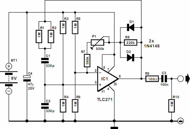
It uses standard components, produces a signal of 899 Hz at an output level of 1 V r.m.s. and draws a current of only 20 µA. In theory, the low current drain would give a 9 V battery a life of 25,000 hours. The circuit is a traditional Wien bridge oscillator based on a Type TLC271 op amp. The frequency determining bridge is formed by C1, C2 and R1–R4. The two inputs of the op amp are held at half the supply voltage by dividers R3-R4 and R5-R6 respectively.
Mini Audio Signal Generator

Resistors R5 and R6 also form part of the feedback loop. The amplification is set to about ´3 with P1. Diodes D1 and D2 are peak limiters. Since the limiting is based on the non-linearity of the diodes, there is a certain amount of distortion. At the nominal output voltage of 1 V r.m.s., the distortion is about 10%. This is, however, of no consequence in fast tests.

Nevertheless, if 10% is considered too high, it may be improved appreciably by linking pin 8 of IC1 to ground. This increases the current drain of the circuit to 640 µA, but the distortion is down to 0.7%, provided the circuit is adjusted properly. If a distortion meter or similar is not available, simply adjust the output to 1 V r.m.s. Since the distortion of the unit is not measured in hundredths of a per cent, C1 and C2 may be ceramic types without much detriment.

Electronics Projects

Pulpit rock