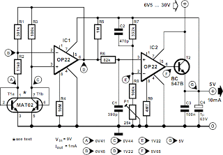
The current drain of the regulator is minute compared with that of, say, a 78L05: at an input voltage of 9 V and open-circuit output, it is just under 50 µA. The circuit consists of a straightforward bandgap reference based on T1 and IC1, followed by an amplifier formed by IC2 and T1. The reference voltage is about 1.22 V, which is raised by IC2 to 5 V. The output voltage can be set to exactly 5 V with P1. The input voltage may lie between 6.5 V and 30 V. The maximum output current with the present configuration and component values as specified is about 10 mA.
For optimum performance, T1a and T1b need to be identical, which is why a dual transtor Type MAT02 is used. Other types that may be used are the MAT01, SSM2210 or LM394. In principle, two standard BC transistors may be used, provided they are selected for identical threshold voltage. Circuits IC1 and IC2 are programmable op amps Type OP22. In the case of IC2 this has the benefit that the peak output current can be set readily by altering the supply current to the op amp with R9. The level of the current may be between 500 nA and 400 µA.
 Bear in mind that a larger output current requires the use of a more highly rated output transistor. Filter R6-C1 prevents any spurious pulses reaching the input of IC2. Capacitor C2 improves the stability of the regulator, particularly with maximum pulse loading. Note that the circuit has a high resistance, so that it is advisable to house it in a screened enclosure to prevent undesired magnetic and electromagnetic interference being coupled to the circuit. The regulator was tested with a direct load current of 1 mA on which was superimposed a square-wave current of 10 mA. The test results are summarized in the table, in which Ig represents the current drawn by the circuit.
For optimum performance, T1a and T1b need to be identical, which is why a dual transtor Type MAT02 is used. Other types that may be used are the MAT01, SSM2210 or LM394. In principle, two standard BC transistors may be used, provided they are selected for identical threshold voltage. Circuits IC1 and IC2 are programmable op amps Type OP22. In the case of IC2 this has the benefit that the peak output current can be set readily by altering the supply current to the op amp with R9. The level of the current may be between 500 nA and 400 µA.

No comments:
Post a Comment